🔧 Solder Your Way to Success!
The GikfunDIY SMD SMT Welding Practice Soldering Skill Training Board Ek7028 is an essential tool for beginners looking to enhance their soldering skills. With a compact design, clear markings, and a user-friendly guide, this training board allows users to connect a power source (3-12V) and instantly see the results of their work, making it an engaging and effective learning experience.
Brand | Gikfun |
Product Dimensions | 12.7 x 8.13 x 0.25 cm; 9.07 g |
Item model number | LYSB00VWB8F8K-ELECTRNCS |
Manufacturer | Esooho |
Series | Ek7028 |
Color | Blue |
Maximum Memory Supported | 1 GB |
Graphics Card Description | Dedicated |
Are Batteries Included | No |
Item Weight | 9.07 g |
A**R
No es para novatos
Te dan un montón de cositas para soldar pero no te dicen que son ni están marcadas para que las coloques donde van
M**I
Brilliant
I've been soldering through hole parts for many years, thinking that SMD was best left to factories with specialized equipment. Working through this kit made me realize that soldering SMD by hand is not only feasible, but actually faster and easier than through hole in my newly-formed opinion.Completing this project was fun and meditative and now I have confidence in this skill and am eager to apply it to a project.The kit has a smart design. Your first 78 parts have no real penalty for mistakes because they are not part of the final "light show" circuit. Yet there are still some basic test points for these areas so you can check your connections with a multimeter. You start with 1206 size components (0.12 x 0.06 inches), then move to 0805, then 0603 and finally 0402. As you would expect, it gets progressively more challenging.After all of that practice, comes the LED blinking circuit. These are all 0805 components which should feel pretty manageable after finishing 0402. A schematic is provided but I never needed it - the board is already marked with what goes where, including the polarity of the LEDs and diodes. I did use the parts table to determine which part values to use. It's also useful to know how to read a SMD resistor code (e.g. 473 = 47,000 ohms).I experimented with a number of different techniques and tools and suggest you do the same, below is a small account of my experiences:Soldering Iron vs Paste + Heat Gun. Between these, I preferred a soldering iron with a small chisel tip.For the paste I was putting it on with a syringe and trying to fix it up with a toothpick - it looked a bit sloppy. For the larger components, it all worked reliably and components "magically" flowed into place. At 0603, about a third of the parts didn't settle correctly and needed corrections with the tweezers and heat gun. At 0402, about half of the parts needed corrections. I think that a solder mask and reflow oven would be quite a different (better) experience here but I don't have either of those.For the soldering iron, I prepped the area with rosin fluid (Kester 951) and held the component in place with some high-quality tweezers. I put a very small amount of solder on the tip and touched the pad, then the corner of the component for less than a second each. I never needed to use the solder wire directly on the board, which is great because I was already using both hands. After doing one side, I put down the tweezers, rotated the board and did the other side in the same way (touch the pad, touch the component side, done). I then went back to the first side and touched it with the soldering iron for another second or so for a finishing step. It takes longer to type this than to actually do it. You can also batch the work by doing one side of a bunch of components, then doing the other side in a followup pass.USB microscope vs headband magnifier (Donegan DA-4). They both worked but I preferred the headband magnifier for several reasons. In short, the headband magnifier was more comfortable to use, the "real" 3D image was nicer than the 2D LCD image and it was nice to easily see where my tools were as I worked. I found the 2x magnification on the magnifier was plenty enough for every case except the 0402, where a little more would be nicer.Silicone work pad. I recommend using one because these pads are heat resistant, and make it easy to see the tiny SMD parts. I placed the board right on the work pad while soldering. This allowed me to use the table to support my hands and keep them more steady during the work.Multimeter. My multimeters will light up an LED in the continuity testing mode. I used this to spot check the LEDs as I installed them, placing the negative probe on the "-" pad at the bottom center of the board and the positive probe on the resistor that is associated with the LED. The correct resistor can be discovered using the multimeter or by looking at the traces under the soldering mask.
M**O
Buono
È buono ma potevano essere 5 stelle ma no si capisce gli smd da montare non sono spigati i valori e come montarli
A**.
Much better quality than I expected!!
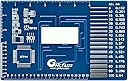
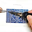
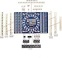
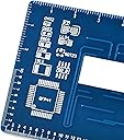
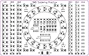
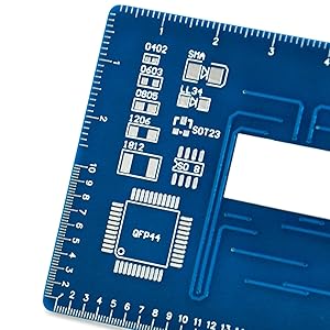
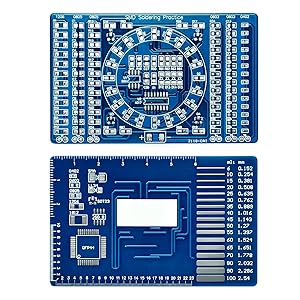
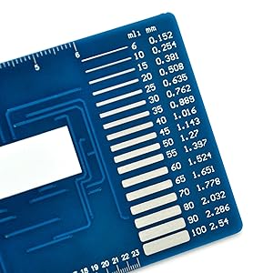
I was very positively surprised by the quality of the included PCB. It's relatively thick, feels very solid, and has very good quality solder mask applied to it.The components themselves came in the usual stripes cut from reels. For most component types, few more were provided then needed, making things easier if one of the SMD components gets lost.The kit comes with a small printed manual, written in English language, which provides basic information on how to do surface-mount soldering, and has several illustrations explaining the steps needed to solder the components, how to identify the correct orientation of the included integrated circuits and diodes, and includes the schematic of the LED Blinker located in the middle of the PCB.The back side of the PCB has several rulers, in centimeters and in 1/10ths and 1/100ths of an inch, as well as examples of several popular PCB trace widths, and popular component footprints.As for the bad sides, there are few small points: The manual seems to be translated from Chinese. In general, grammar of the translation is very good, and manual is easy to understand, however few technical terms have been incorrectly translated: The manual always refers to the procedure as welding, instead of soldering, and it refers to the transistors as triodes. The direction of the SMD LEDs is not shown on the silkscreen, so it needs to be manually determined by following the traces on the board and using the included circuit schematic. Additionally, the measurement unit of 1/1000 of an inch is misspelled as mli instead of mil on the back side of the PCB.All in all, this is a great kit, but it does require some very basic knowledge of electronics.
M**L
Good for new skills or brushing up on old ones
Although I think this could be cheaper I think it gets the job done for learning new skills or brushing up on old ones.I bought this to brush up on some soldering after some time leaving university doing electronics. I thought it was a good quality board. Easy enough to do with some patience. I used 0.6mm diameter solder with a thin tip iron and a pair of helping hands. I say easy enough to do I have bought 3 of these since the first two I messed up. Put the polarity of some components the wrong way round and second one put the battery the wrong way round... Best to check to be sure to save yourself money.Instructions arent as easy to follow as they could be but all works one you finished.
Trustpilot
1 month ago
1 month ago