


Buy anything from 5,000+ international stores. One checkout price. No surprise fees. Join 2M+ shoppers on Desertcart.
Desertcart purchases this item on your behalf and handles shipping, customs, and support to Hungary.
๐ Connect with Confidence!
The HiLetgo 3pcs TLP281 Optocoupler Isolation Board is a high-performance optical coupler isolation module designed for seamless integration between low-voltage digital systems and high-voltage or noisy environments. With a compact size and reliable signal handling, this module is perfect for engineers and hobbyists looking to enhance their projects.
| ASIN | B01MRR4K6Z |
| Best Sellers Rank | #263,428 in Industrial & Scientific ( See Top 100 in Industrial & Scientific ) #37 in Optocouplers |
| Brand | HiLetgo |
| Built-In Media | 3 * TLP281 Optical Coupler Isolation Module |
| Compatible Devices | Single-board computers |
| Customer Reviews | 4.5 out of 5 stars 19 Reviews |
| Included Components | 3 * TLP281 Optical Coupler Isolation Module |
| Manufacturer | HiLetgo |
| Mfr Part Number | 3-01-1180 |
| Model Name | TLP281 |
| Model Number | 3-01-1180 |
| Number of Packs | 3 |
| Smart Home Compatibility | Not Smart Home Compatible |
| Unit Count | 9.0 Count |
P**S
Small, affordable, functional.
Small, affordable, functional. Whatโs not to like. Iโm using these to create a Raspberry Pi monitor and log for mains power outages.
A**R
TLP281 opto-isolator helped me isolate my 4 bit shift register from the stepper motor driver board
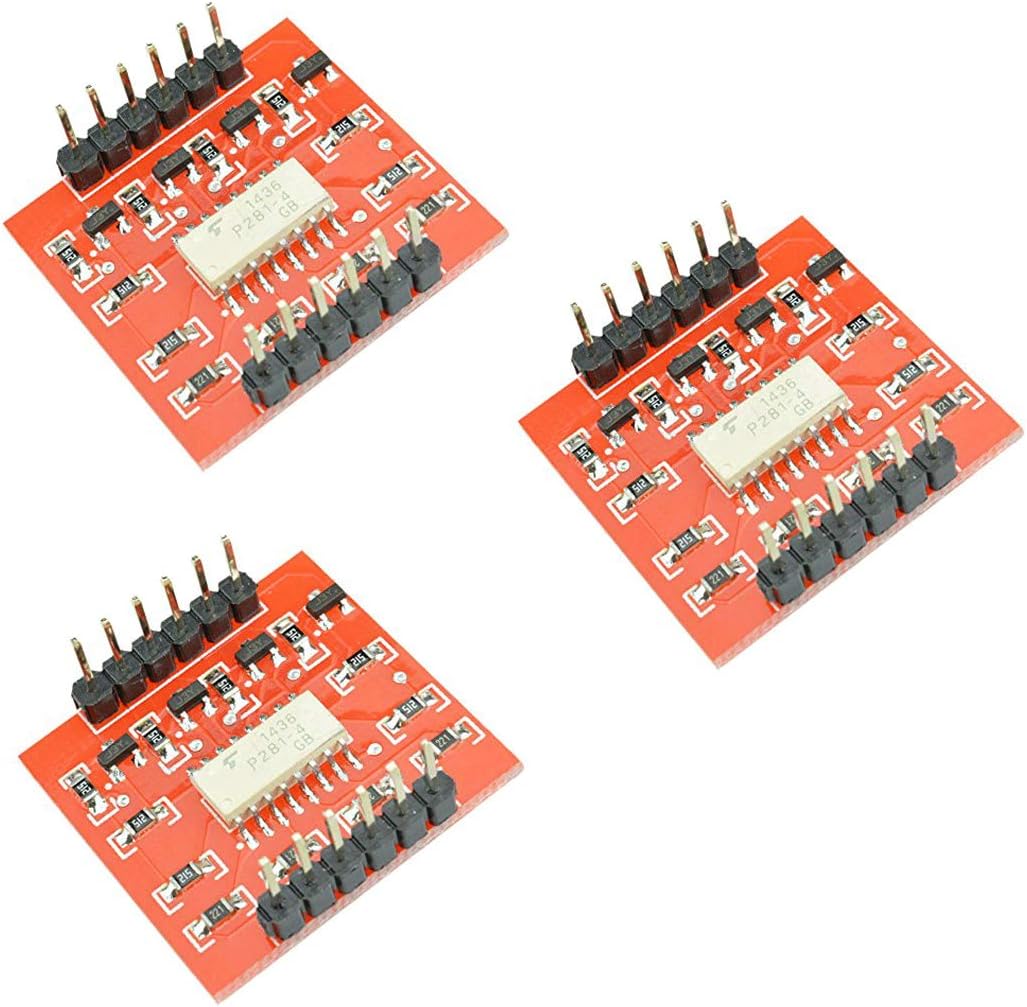
I found a great solution to isolate my 4 bit universal shift register 74LS194 from the bipolar stepper motor driver board. My signals 1100, 0110, 0011, 1001, back to 1100 , etc were used to drive my H- bridge stepper motor driver board 9001 . The driver was connected to our pancake 5 volt bipolar stepper motors. Unfortunately, my students and I were burning out the driver boards as we often test or troubleshoot our circuitry. Our solution was to use the TLP281 opto-isolator board to couple the shift register signals to the stepper motor driver board. Since then, we have not burnt out any of our H - bridge driver boards or damaged the shift register output pins 12,13,14,15 on the 74LS194. Now, our stepper motor controller system works great and the opto-isolator boards were helpful in the reliable circuit design. I strongly reccomend trying this opto-isolator board out for any switching that requires the type of isolation that is mentioned above.
P**.
Good Cheap Optocoupler
Great little optocoupler to connect 5V and 3V systems together. Simple to use. No instructions but if you get one of these hopefully you know how to use it. (I'm using a 5V Arduino to trigger a 3V GPIO pin on a Raspberry Pi SBC.)
D**3
Not enough current to drive an LED
The product does work, but not without adding an external transistor to drive a simple LED. While the product does provide isolation, it is ineffective if it can't drive any significant output. The intention was to use this to drive multiple isolated outputs. Since it was ineffective, I was forced to design my own set of 4n25 opto circtuits. I would NOT purchase this again.
F**T
Can be driven at 5vDC
Just a note - you can drive input and output at 5vDC just fine - you don't need the full 24V indicated in the drawing. Also, you can drive these at about 5-8KHz before the output Hi and Lo are no longer the same amount of time. These are perfect for optoisolation by sitting between your limit switches and CNC controller PCB.
C**M
The device has a 32us off-delay at 5V Vcc. 4us at 10V+.
If you're planning on using this for 5V Vcc, know that the off-time is around 30-40us. Pic is 5V, 5kHz, 50% Duty Cycle. For things like limit switches, this would be fine. But for anything that requires timing at 5V, it's useless if you care about the output going low at the right time.
B**N
Test them first!
So, I had a problem with one out of three of these in my first order: the 4th channel had reversed polarity. I shrugged, because they are very inexpensive, and got three more to have spares. Well, so far, the first one channel 1 is dead, and the second one, only channel 3 works. I haven't tested the third yet. So, this is a very simple circuit, and honestly, if I could get say 4-5 out of 6 working, I wouldn't care at the price point. But 50% bad? That's not good enough.
N**.
simple design. perfect for my relay circuit
I was designing a simple arrays of Relay circuits. This meet my need perfect with 4 channels. it has 4 opto-couplers and 4 transistors. It will provide low output when you give it a high TTL signal.
Trustpilot
1 day ago
2 months ago